
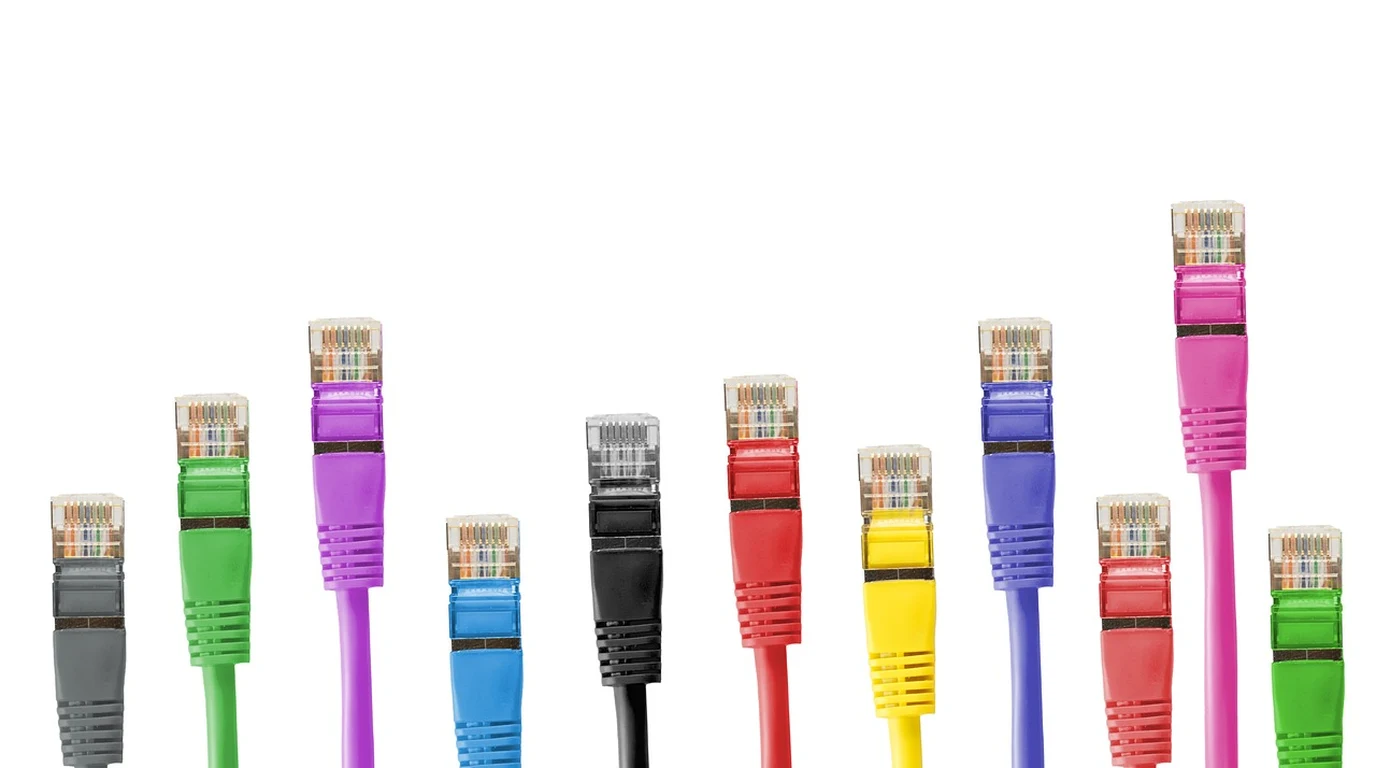
In physical security and IP surveillance architecture, the physical cable drop is the single most critical, yet frequently compromised, component of the entire installation. High-resolution 4K optical sensors, high-draw infrared arrays, pan-tilt-zoom (PTZ) servo motors, and internal lens defogging heaters all depend on a continuous, uninterrupted stream of both Gigabit data and direct-current electrical power delivered through a single eight-conductor twisted pair cable. When security integrators treat camera cabling as an afterthought—pulling cheap, unshielded bulk Cat5e or sub-gauge Cat6 through exterior walls and attic spaces—the inevitable result is dropped RTSP video frames, erratic camera reboots under nighttime IR load, and catastrophic port failures during regional electrical storms.
Should You Run Cat6 UTP or Cat6A STP for PoE Cameras?
Direct Cabling Verdict: Cat6 vs. Cat6A for Surveillance
For indoor cameras and short attic runs under 50 meters, standard 23 AWG pure copper Cat6 UTP (Unshielded Twisted Pair) provides flawless performance. For all exterior soffit cameras, outdoor pole mounts, runs parallel to high-voltage conduit, or high-power 802.3bt Type 3/4 PTZ cameras, Cat6A F/UTP or STP shielded cable with single-point rack bonding is mandatory to prevent DC voltage drop and electromagnetic surge damage.
The operational demands placed on modern PoE security cameras have shifted radically over the past five years. Legacy 1080p surveillance cameras drew a modest 4 to 7 watts under the baseline IEEE 802.3af (PoE) standard, creating negligible resistive heating across copper conductors. In contrast, modern 4K commercial turrets, multi-sensor 180-degree panoramic arrays, and long-range motorized PTZ cameras utilize IEEE 802.3at (PoE+, up to 30W) and IEEE 802.3bt (PoE++, up to 60W or 90W). At these high continuous wattages, conductor gauge, copper purity, and shielding geometry directly dictate whether your cameras stay online or suffer from thermal dropouts.
The Physics of PoE Voltage Drop and Resistive Heating
Every electrical conductor presents intrinsic resistance to direct current flow. The total loop resistance of a twisted pair cable is determined by Ohm’s Law and Joule heating ($P = I^2 R$). As PoE wattage increases from 15.4W to 60W, the electrical current traveling down the cable increases from approximately 350mA to nearly 1,000mA per conductor pair.
When high current passes through thin copper conductors, two physical phenomena occur:
- DC Voltage Drop Across Distance: Power over Ethernet switches deliver nominal 48V to 54V DC at the switch port. Over an 80-meter cable run, conductor resistance causes voltage drop. If the voltage arriving at the camera terminal drops below the minimum operating threshold (typically 37V DC for 802.3af/at devices), the camera’s internal DC-to-DC converter fails, causing the camera to reboot. This frequently manifests as “the night-vision reboot loop”: the camera functions perfectly in daylight, but the second the ambient light sensor triggers high-power infrared LEDs at dusk, current demand spikes, voltage collapses, and the camera drops offline.
- Cable Bundle Thermal Rise: When 24 or 48 PoE cables are bundled tightly together in cable trays or server rack vertical raceways, the heat generated by conductor resistance cannot easily dissipate. In standard Cat5e or thin-gauge Cat6 (24 or 26 AWG), bundle core temperatures can rise by 15°C to 20°C above ambient. This thermal rise increases high-frequency signal attenuation, introducing bit errors and packet loss into RTSP video streams.
| Cable Category & Shielding | Conductor Gauge (AWG) | Max Continuous PoE Standard | EMI & Transient Immunity | Max 10G / 1G Distance | Recommended Surveillance Zone |
|---|---|---|---|---|---|
| Cat5e UTP (Legacy Baseline) | 24 AWG (High resistance) | 802.3af (15.4W max) | Poor (Zero shielding) | 1G @ 100m (10G unsupported) | Obsolete; avoid on new deployments |
| Cat6 UTP (Standard Solid Bare Copper) | 23 AWG (Moderate resistance) | 802.3at PoE+ (30W) | Moderate (Internal spline cross) | 10G @ 37–55m / 1G @ 100m | Indoor domes, offices, short attic drops (<50m) |
| Cat6A F/UTP (Foiled / Unshielded Pairs) | 23 AWG (Low resistance) | 802.3bt Type 3 (60W) | Excellent (Overall foil shield) | 10G @ 100m / 1G @ 100m | Exterior soffits, commercial runs, multi-sensor 4K |
| Cat6A S/FTP (Braided + Foiled Pairs) | 22–23 AWG (Lowest resistance) | 802.3bt Type 4 (90W) | Maximum (Individual foil + braid) | 10G @ 100m / 1G @ 100m | Industrial plants, elevator shafts, high-power PTZ |
| Outdoor Direct Burial CMX Cat6A | 23 AWG (UV & Water-blocked) | 802.3bt Type 3/4 (60W–90W) | Superior (Foil + gel / tape) | 10G @ 100m / 1G @ 100m | Perimeter gates, outbuilding trenching, pole mounts |
Costly Cabling Traps: Copper-Clad Aluminum and Ground Loop Disasters
When running infrastructure drops for surveillance cameras, installers must steer clear of two fatal traps that destroy hardware:
1. The Copper-Clad Aluminum (CCA) Nightmare
The single most dangerous material in structured cabling is Copper-Clad Aluminum (CCA) wire, often sold fraudulently online as budget bulk Cat6. CCA replaces pure solid electrolytic copper with an aluminum core coated with a microscopically thin exterior sleeve of copper. Aluminum has 55% higher electrical resistance than pure copper. Under continuous 802.3at or 802.3bt PoE loads, CCA cables experience extreme I²R heat dissipation, causing the cable insulation to become brittle, creating dangerous fire hazards inside walls, and dropping voltage so severely that cameras malfunction. Always verify that bulk cable carries the UL Verified mark and specifies 100% Solid Bare Copper (BC).
2. The Double-Ended Shield Ground Loop Trap
Deploying shielded Cat6A (STP/FTP) cable requires strict adherence to single-point electrical grounding. If an installer grounds the shield drain wire at both ends of the run—connecting the metallic RJ45 connector to a metal outdoor camera enclosure at a detached garage and also connecting it to the grounded server rack in the main residence—a ground loop differential is created. Because the electrical earth potential between the two structures differs by several volts, continuous parasitic stray current circulates through the cable shield. This introduces 60Hz hum into audio streams, causes packet dropouts, and provides a direct path for lightning surges to travel straight into the network switch.
The 4:00 PM Actionable Surveillance Cabling Playbook
Follow this exact numbered procedure when terminating and commissioning camera cable drops across an estate:
- Zone-Based Cable Selection: Pull 23 AWG Solid Bare Copper Cat6 UTP with an internal polyethylene spline for all interior ceiling drops and attic runs under 50 meters. Pull 23 AWG Cat6A F/UTP with an overall foil shield and UV-rated outdoor jacket for all exterior roofline, soffit, and conduit installations. For trenching to perimeter gate cameras, pull gel-filled CMX direct-burial Cat6A.
- Implement Single-Point Star Grounding: Terminate all exterior shielded Cat6A drops into a shielded 1U rack-mount patch panel inside the equipment room. Bond the patch panel’s grounding lug directly to the central equipment rack ground busbar using 6 AWG copper wire. At the camera end, float the shield—do not bond the metallic shield to local exterior building earth.
- Install Exterior Gas-Tube Surge Protection: On all cable runs entering the residence from exterior poles, outbuildings, or fence lines, install an inline PoE-rated Gas Discharge Tube (GDT) lightning surge protector (such as a Ubiquiti ETH-SP-G2) right at the building envelope entry point, bonded directly to the main building grounding electrode conductor.
- Maintain Bend Radii and Pair Untwist Standards: When dressing Cat6A cable inside junction boxes and patch panels, maintain a minimum bend radius of 4 times the cable outer diameter (approximately 1.25 inches). When terminating into RJ45 jacks, never untwist the internal pairs more than 0.25 inches (6mm) to preserve common-mode rejection and prevent near-end crosstalk (NEXT).
- Certify with a Time-Domain Reflectometer (TDR): Test every finished drop using a professional cable certifier (such as a Fluke MicroScanner or CableIQ). Verify wire-map continuity, confirm zero split pairs, verify DC loop resistance under 12 ohms, and verify Gigabit/10G signal-to-noise ratio before plugging cameras into the PoE switch.
Reliable physical camera drops form the essential data pipeline for edge AI video analytics. Read our satellite hardware benchmark in Local Whisper Satellites: ReSpeaker vs ESP32-S3 Box 3.