
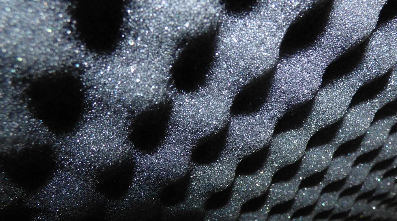
You have spent thousands of dollars on reference-grade studio monitors, a pristine digital-to-analog converter, and hours meticulously aligning your speaker placement to the millimeter. Yet, when you play a track with a dense low-end kick or sit down to audit a cinematic dialogue mix, something feels profoundly off. Low frequencies smear across the room, vocals sound recessed or boxy, and complex musical passages collapse into a muddy wall of sound. In desperation, you buy a few boxes of two-inch thin acoustic foam, slap them on the side walls, and find that your room now sounds uncomfortably dead at high frequencies while remaining overwhelmingly boomy at the bottom end.
This is the classic acoustic trap. You are fighting physics with thin open-cell foam, treating the wrong frequency bands, and ignoring the foundational math of room acoustics: Reverberation Time (RT60). Tuning a room is not an art of deadening sound; it is an engineering discipline of controlling energy decay across time and frequency. Let’s sit down, grab a cup of coffee, and walk step-by-step through the exact mathematics, measurement tools, and physical treatment strategies required to calculate, measure, and master your room’s RT60 decay profile.
To optimize room decay time (RT60), target 0.25–0.35s for home cinemas and 0.40–0.50s for two-channel listening rooms. Calculate targets using Eyring’s formula rather than Sabine’s for treated spaces. Combine boundary-mounted diaphragmatic pressure traps for room modes below 100 Hz with 4-inch-thick porous velocity absorbers placed at reflection points for energy above 250 Hz.
What Is Room Decay Time RT60 and Why Do Your Targets Keep Overlapping?
At its core, RT60 (Reverberation Time 60 dB) represents the exact duration in seconds required for sound pressure level (SPL) to decay by 60 decibels after the excitation sound source abruptly stops. Standardized under ISO 3382-1, this metric quantifies how long acoustic energy bounces between boundary walls, floor, and ceiling before dissipating into thermal energy.
In smaller residential spaces—such as dedicated home theaters, mixing suites, or hi-fi listening rooms—measuring a full 60 dB drop directly can be challenging due to ambient noise floors (e.g., HVAC noise or electrical background noise sitting at 35–40 dBA). To solve this, software tools like Room EQ Wizard (REW) extrapolate RT60 using shorter decay intervals:
- EDT (Early Decay Time): Measured over the initial 0 to -10 dB decay range. EDT correlates heavily with perceived acoustic clarity and subjective room volume.
- T20: Measured from -5 dB to -25 dB of decay and multiplied by 3 to project the full 60 dB decay time. T20 removes initial early reflections from the decay slope calculation.
- T30: Measured from -5 dB to -35 dB of decay and multiplied by 2. T30 offers the standard engineering reference when your measurement signal-to-noise ratio exceeds 45 dB.
A common point of confusion arises when determining your target RT60 line across the audible spectrum (125 Hz to 4,000 Hz). The ideal target depends entirely on how you intend to use the space:
Target RT60 Profile Guidelines Across Use Cases
Dedicated Home Cinema / Atmos Suite: 0.25s – 0.35s (Flat within ±0.05s down to 125Hz; gentle rise allowed below 80Hz).
Why? Multichannel film soundtracks rely on discreet spatial positioning embedded in the audio mix. Excessive room decay causes speech formant smearing, destroying dialogue intelligibility and masking subtle surround channel panning cues.
Two-Channel Audiophile / Hi-Fi Room: 0.40s – 0.50s (Flat within ±0.05s from 250Hz to 4kHz; slight rise up to 0.60s below 100Hz).
Why? Two-channel stereo recordings count on a controlled degree of natural room envelopment. A room that is too dry (RT60 < 0.25s) destroys musical warmth, leaving acoustic instruments, vocals, and soundstage depth feeling thin and artificial.
How Do You Calculate RT60 Using Sabine vs. Eyring Formulas?
Before buying a single sheet of rockwool or building a custom acoustic frame, you must perform initial boundary estimations using mathematical room models. Historically, room decay calculation relies on two distinct classical equations: Wallace Clement Sabine’s formula and Carl F. Eyring’s formula.
1. Sabine’s Classical Formula
Sabine’s formula assumes an acoustic field that is perfectly diffuse, where sound energy is evenly distributed throughout the room volume. In metric units, Sabine’s formula is expressed as:
RT60 = (0.161 × V) / A
Where:
V= Room Volume in cubic meters (m³)A= Total Equivalent Absorption Area in square meters metric Sabins (m² Sabin)0.161= Constant accounting for the speed of sound in air at 20°C
The total equivalent absorption area (A) is calculated by summing the surface area of each room material multiplied by its specific absorption coefficient (α) at a given frequency band:
A = (S₁ × α₁) + (S₂ × α₂) + (S₃ × α₃) + … + (Sₙ × αₙ)
Where S represents boundary surface area (m²) and α represents the sound absorption coefficient ranging from 0.00 (100% reflective) to 1.00 (100% destructive absorption).
2. Eyring’s Formula for Heavily Treated Spaces
Sabine’s equation breaks down when applied to small, highly treated critical listening environments. Because Sabine assumes low average absorption across all boundaries, it overestimates decay time when total room absorption increases. If a room were covered entirely in 100% absorbing material (α = 1.0), Sabine’s math produces a non-zero decay time, which violates physical realities.
Eyring corrected this flaw by factoring in energy loss per reflection wave boundary hit. Eyring’s formula is expressed as:
RT60 = (0.161 × V) / [ -S × ln(1 – αavg) ]
Where:
S= Total surface area of all room boundaries combined (m²)αavg= Average absorption coefficient of the space (A / S)ln= Natural logarithm
When engineering a small media room or home theater where target average absorption (αavg) exceeds 0.25, always use Eyring’s formula. Using Sabine’s formula in treated spaces leads to under-treating low frequencies and over-treating mid-to-high frequencies.
Why Does Velocity Absorption Fail Below 100 Hz?
To successfully hit a uniform RT60 target curve from 63 Hz to 8,000 Hz, you must understand the fundamental physical divergence between two distinct absorber classes: Velocity Absorbers and Pressure Absorbers.
[ Boundary Wall ] ————————————————————-
PRESSURE | MAX (100%) |||||||||||||||| (Room Modes / Standing Waves)
VELOCITY | ZERO ( 0%) ……………. (Porous panels ineffective)
|
λ / 4 Distance | (~3.5 ft at 80Hz)
PRESSURE | MIN ( 0%) …………….
VELOCITY | MAX (100%) |||||||||||||||| (Porous panels highly effective)
——————————————————————————-
Velocity Absorbers (Open-Cell Porous Materials)
Porous materials—such as semi-rigid mineral wool (e.g., Rockwool Safe’n’Sound, Owens Corning 703/705) and open-cell acoustic foam—dampen sound by causing air particles to rub against fine fiber structures. This friction converts particle kinetic energy into minute amounts of heat.
However, particle velocity drops to zero right at rigid room boundaries (walls, floor, ceiling), while acoustic pressure reaches its maximum. For a porous absorber to function efficiently, it must be placed where air particle velocity is high. Maximum particle velocity occurs at one-quarter wavelength (λ/4) away from the boundary wall.
Let me show you why thin porous panels fail at low frequencies:
- At 1,000 Hz, the wavelength (
λ) is approximately 1.13 feet (34.3 cm). The λ/4 point sits just 3.4 inches (8.6 cm) from the wall. A standard 4-inch panel easily spans this point, absorbing mid-range energy efficiently. - At 63 Hz, the wavelength (
λ) expands to 18 feet (5.49 m). The λ/4 maximum velocity point sits 4.5 feet (1.37 meters) away from the wall.
Slapping a 2-inch or 4-inch porous panel directly against a boundary wall places it in a high-pressure, zero-velocity region. The panel is completely transparent to the 63 Hz wave, leaving low-frequency modal ringing untouched while stripping away high-frequency air. This leads directly to the dreaded “dead yet boomy” room signature.
Pressure Absorbers (Resonant Damped Systems)
To control low-frequency decay times below 100 Hz without wasting feet of floor space, you must deploy pressure-based resonant absorbers directly on room boundaries where acoustic pressure peaks:
- Diaphragmatic / Sealed Membrane Traps: Consist of an airtight sealed enclosure backed by a dense, floating mass membrane (typically limp-mass vinyl or thin steel) mounted over an internal porous absorber core. Incoming pressure waves flex the membrane, driving internal structural friction that rapidly drains acoustic energy at the cabinet’s resonant frequency.
- Helmholtz Resonators: Consist of a rigid chamber connected to the room via tuned ports or perforated face plates. The air in the port acts as a dynamic mass oscillating against the elastic spring volume of air trapped inside the cavity. When tuned precise to problem room modes, Helmholtz traps absorb low-end energy rapidly across tight bandwidths.
Comparing Acoustic Treatment Types and Performance Characteristics
To help you select the right acoustic treatments for your target RT60 profile, the matrix below breaks down physical mechanisms, target frequency ranges, placement requirements, and common pitfalls:
| Treatment Class | Primary Physics Mechanism | Target Frequency Range | Optimal Room Placement | Common Installation Errors |
|---|---|---|---|---|
| 2-Inch Porous Foam / Fiberglass | Velocity (Particle Friction) | 1,000 Hz – 20,000 Hz | Side wall secondary reflection points | Over-applying to solve low-end boom; deadens air while leaving decay uneven. |
| 4-Inch Rigid Mineral Wool (703/705) | Velocity (Viscous Resistance) | 250 Hz – 20,000 Hz (125 Hz with air gap) | First reflection points & ceiling clouds | Mounting flush against hard backing without an internal air gap. |
| Corner-Straddled Bass Traps | Hybrid Velocity / Gas Resistance | 100 Hz – 1,000 Hz | Tri-fold vertical wall/ceiling junctions | Using light 16kg/m³ density insulation that lacks core flow resistivity. |
| Diaphragmatic Membrane Traps | Pressure (Mass-Spring Damping) | 35 Hz – 125 Hz (Narrowband) | Maximum pressure boundary intersections | Failing to form an airtight seal around cabinet internal frames. |
| QRD 1D/2D Quadratic Diffusers | Phase-Shift Energy Dispersion | 500 Hz – 8,000 Hz | Rear room walls & center ceiling boundaries | Sitting closer than 3x maximum design wavelength from listener position. |
Standard Acoustic Absorption Coefficients (α) Reference Table
When calculating Sabine or Eyring decay predictions, use real-world laboratory measurement data across standard 1/1 octave bands:
| Material / Surface Description | 125 Hz | 250 Hz | 500 Hz | 1000 Hz | 2000 Hz | 4000 Hz | NRC |
|---|---|---|---|---|---|---|---|
| Gypsum Board (1/2″ on studs) | 0.29 | 0.10 | 0.05 | 0.04 | 0.07 | 0.09 | 0.07 |
| Standard 1/4″ Window Glass | 0.35 | 0.25 | 0.18 |
|