
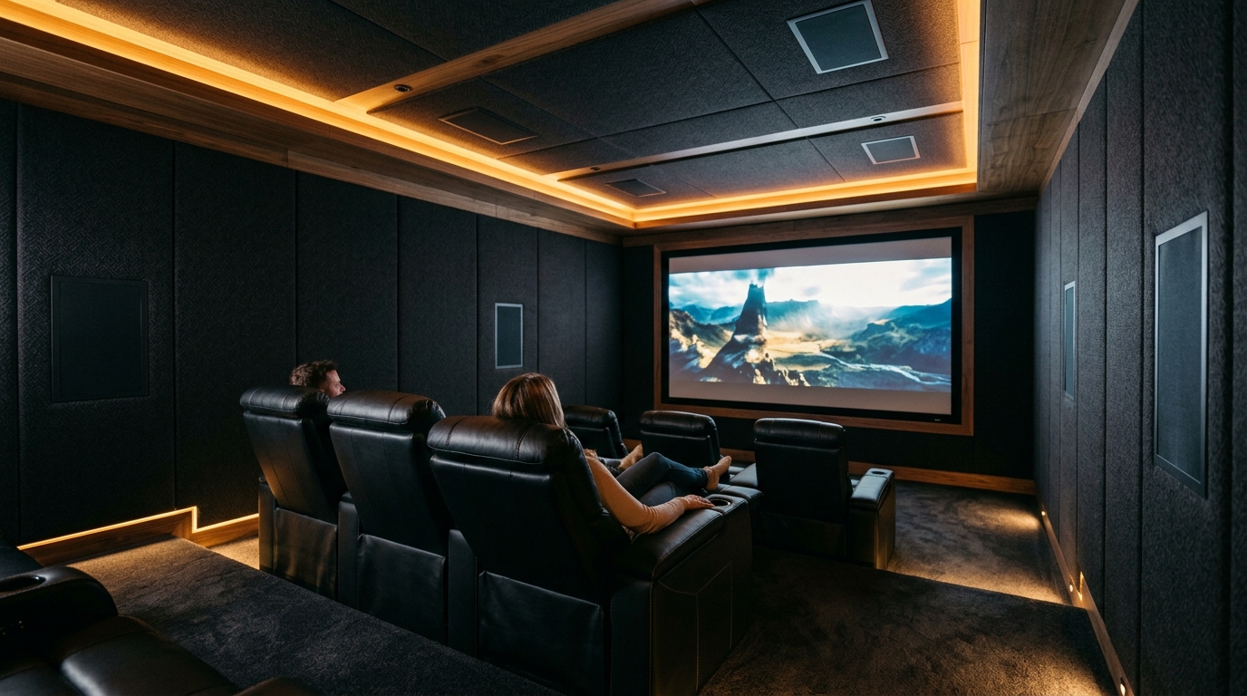
- Acoustic Spatial Geometry: Standard 7.2.4 layouts provide basic 3D hemispherical sound, but suffer from significant acoustic localization gaps between the front stage (LCR) and side surrounds (90°–110°). The 9.4.6 topology introduces Front Wides (55°–65°) and Middle Top/Height channels (80°–100°), closing spatial trajectory dips for seamless object pans.
- Trinnov 3D Optimization & Remapping: When architectural obstacles (bulkheads, HVAC ducts, sightlines) force physical speaker placement off strict Dolby azimuth/elevation angles, 3D remapping engines (Trinnov Optimizer, StormAudio ISP) utilize 4-capsule 3D calibration microphones to triangulate physical acoustic coordinates and vector-synthesize ideal virtual acoustic origins.
- Acoustical Baffle Wall Integration: Flush-mounting LCR and subwoofer arrays into an engineered stud-and-damping baffle wall eliminates boundary interference (SBIR – Speaker Boundary Interference Response), yielding +6dB of free low-frequency acoustic gain and pristine transient punch.
- Infrastructure Integration: Pairs natively with multi-subwoofer calibration workflows such as Dirac Live Bass Control (DLBC) vs. Multi-Sub Optimizer (MSO) and high-bandwidth 8K AV-over-IP distribution networks.
In the luxury residential theater domain, the difference between a consumer home theater and a true private cinema does not lie in how many watts an amplifier outputs or how massive a display screen appears. It is dictated entirely by spatial acoustic geometry, object-based rendering resolution, and room boundary control. While commercial marketing frequently bundles any soundbar with upward-firing drivers under the “Dolby Atmos” banner, true reference immersive audio requires rigorous adherence to CEDIA/CTA-RP22 (Immersive Audio Design) guidelines.
For cinema designers and systems architects planning high-end residential installations in 2026, the primary structural crossroads is choosing between an entry reference 7.2.4 architecture (7 bed layer, 2 subwoofers, 4 overhead heights) and a full-scale reference 9.4.6 architecture (9 bed layer, 4 directional subwoofers, 6 overhead heights). Below, we break down the engineering math, physical dispersion physics, in-ceiling elevation tolerances, processor DSP requirements, and acoustic baffle wall construction required to achieve cinematic perfection.
1. The Geometric Comparison: 7.2.4 vs. 9.4.6 Spatial Coordinates
Object-based audio formats (Dolby Atmos, DTS:X Pro, Auro-3D) do not record channels; they record audio objects positioned in a virtual three-dimensional vector space accompanied by spatial metadata. The audio processor’s rendering engine calculates in real-time how much energy to send to each physical speaker to place that sound object at the intended coordinates.
When a sound object pans across a theater, the processor crossfades between adjacent speakers. If the physical distance or angular separation between two adjacent speakers exceeds 60 degrees, human auditory localization collapses—a psychoacoustic phenomenon known as the spatial imaging collapse. The sound appears to jump abruptly from one enclosure to the next rather than sweeping seamlessly through space.
| Acoustic Parameter | Reference 7.2.4 Topology | Reference 9.4.6 Topology | Acoustic Impact & Engineering Rationale |
|---|---|---|---|
| Bed Layer Channel Count | 7 Speakers (LCR, Side L/R, Rear L/R) | 9 Speakers (LCR, Front Wide L/R, Side L/R, Rear L/R) | Front Wides eliminate the 60°–80° acoustic blindspot between front soundstage and side surrounds. |
| Overhead Height Channels | 4 In-Ceiling (Top Front L/R, Top Rear L/R) | 6 In-Ceiling (Top Front L/R, Top Middle L/R, Top Rear L/R) | Top Middle drivers maintain overhead trajectory continuity directly above primary listening row. |
| Subwoofer Topology | 2 Discrete LFE/Bass Channels | 4 Discrete Spatial/Directional Subwoofers | Enables quad-corner or DBA (Double Bass Array) room mode cancellation down to 10Hz. |
| Angular Coverage Gaps | Up to 70° gap between Front Left/Right and Side Surrounds | Under 35° continuous angular spacing around listening circle | Seamless vector panning without audible perceptual energy dips. |
| Optimal Room Dimensions | Under 350 sq ft (14 ft x 22 ft x 9 ft) | 450 to 1,200+ sq ft (18 ft x 28 ft x 10 ft+) | Larger volumetric enclosures require physical speaker density to avoid phase smearing. |
| Minimum Processor Channels | 11–13 Channel AVR (e.g., Denon AVR-X3800H/X6800H) | 16–24 Channel Preamp Processor (Trinnov Altitude 16/32, StormAudio ISP) | Requires discrete DACs, balanced XLR outputs, and high-performance DSP clocking. |
2. The Critical Role of Front Wides and Top Middle Channels
Many enthusiasts assume that expanding beyond 7.1.4 simply means “adding more volume.” In reality, the two specific speaker additions in a 9.4.6 layout solve distinct psychoacoustic limitations:
Front Wide Speakers (55° to 65° Azimuth)
In a 7-channel bed layer, Left and Right main speakers sit at roughly 22° to 30° off-center, while Side Surrounds sit at 90° to 110°. This leaves an acoustic chasm of 60° to 80° on either side of the listener. When an object—such as an aircraft flying from the front soundstage to behind the viewer—traverses this gap, the sound collapses into the side wall before re-emerging. Front Wides, positioned precisely between 55° and 65°, anchor the transition, providing continuous physical driver coupling as the object pans across the screen periphery.
Top Middle Overhead Speakers (80° to 100° Elevation)
In a 4-overhead Atmos configuration (.4), speakers are placed at Top Front (45° elevation forward) and Top Rear (135° elevation behind). While effective for single-row seating, in multi-row theaters, the geometric center of the ceiling directly above the primary listening position (the “sweet spot”) lacks a physical sound radiator. When an overhead object hovers dead-center overhead, phantom imaging can become diffuse. Adding Top Middle speakers at 80° to 100° elevation solidifies the zenith point of the acoustic dome, delivering razor-sharp overhead precision.
3. In-Ceiling Polar Dispersion & Elevation Angle Geometry
One of the most catastrophic installation errors in residential home theaters is mounting standard architectural in-ceiling speakers that fire straight down at the floor (0° axis). High frequencies (above 3 kHz) become increasingly directional. A speaker mounted flush with a 9-foot ceiling firing downward will direct its primary acoustic energy cone onto the floor, leaving the seated listener 30° to 45° off-axis. The listener experiences severe high-frequency rolloff (often -8dB to -14dB at 10 kHz), destroyed transient clarity, and muffled dialog cues.
All overhead speakers must provide either an angled baffle (typically 15° to 30° angled architectural speakers from manufacturers like Triad, Wisdom Audio, or KEF) or broad, controlled polar dispersion (minimum 100° conical dispersion to -6dB). The acoustic axis of every height channel must be aimed directly at the primary listening ear height (typically 38 inches to 42 inches from the finished floor).
To calculate the precise in-ceiling speaker positioning relative to the Primary Listening Position (PLP):
- Top Front Height Distance: \(D_{TF} = H_{ceiling} imes an(90° – heta_{TF})\), where \( heta_{TF}\) is the target elevation angle (recommended 45°). In a room with 9 ft ceilings (listening ear at 3.5 ft, delta = 5.5 ft), the Top Front speakers must be placed exactly 5.5 feet forward of the listening position.
- Top Middle Height Distance: Centered within ±5° of the listener’s ear plane along the length axis, spaced laterally between 0.5x and 0.7x of the room width.
- Top Rear Height Distance: Positioned identically to Top Front, but 5.5 feet rearward of the listening row (elevation angle 135°).
4. Trinnov 3D Optimization & Spatial Acoustic Remapping
In real-world residential architecture, perfection is frequently challenged by physical reality: structural steel beams, HVAC return ducts, structural posts, light fixtures, and doorway openings routinely prevent speakers from occupying ideal CEDIA/Dolby coordinates. This is where advanced processors like the Trinnov Altitude 16/32 and StormAudio ISP Elite completely outclass commercial AVRs.
Trinnov’s proprietary 3D Remapping utilizes a calibrated 3D tetrahedral microphone containing four omnidirectional capsules spaced precisely a few centimeters apart. During measurement sweeps, the processor performs time-difference-of-arrival (TDOA) analysis to determine the exact 3D spatial coordinate \((X, Y, Z)\) of every physical voice coil in the room to within 1 centimeter and 1 degree of azimuth/elevation.
When a Dolby Atmos soundtrack directs a sound to a specific virtual coordinate, Trinnov’s 3D remapping algorithm determines that no physical speaker sits at that precise point. Instead of dropping the object to the nearest misplaced driver, Trinnov applies vector base amplitude panning (VBAP) across the two or three closest physical speakers, adjusting phase and impulse alignment down to fractions of a millisecond. The human ear perceives the acoustic source as originating exactly from the theoretical Dolby reference coordinate.
5. Acoustic Baffle Wall (THX-Style) Construction Behind the Screen
No discussion of reference home theater design is complete without examining the front soundstage. In commercial cinema design (and ultra-luxury residential screening rooms), the Left, Center, and Right (LCR) speakers and subwoofers are never placed on stands or inside loose cabinetry behind an Acoustically Transparent (AT) woven screen. They are flush-mounted into an engineered acoustical baffle wall.
- Elimination of SBIR (Speaker Boundary Interference Response): When a freestanding speaker radiates sound, low-frequency sound radiates omnidirectionally (4π space). The sound waves wrap around the cabinet, strike the rear wall, and reflect forward. These reflected waves collide out of phase with the direct sound, creating massive notches (cancellations of -15dB to -25dB) between 60Hz and 250Hz that no DSP EQ can ever correct. Flush-mounting the speaker into a continuous rigid plane forces all acoustic radiation forward into 2π space, completely abolishing SBIR notches.
- +6dB Boundary Sensitivity Boost: Confining radiation to 2π half-space yields up to +6dB of acoustic gain in the lower octaves. This cuts amplifier power demands in half and dramatically lowers voice-coil thermal compression.
- Pristine Transient Attack: Massive 2-inch multi-layer MDF and drywall baffle walls, heavily braced and damped with Green Glue and mineral wool, prevent cabinet resonance from blurring dialogue articulation.
6. Frequently Asked Questions (PAA Protocol)
Can an existing 7.2.4 AVR be expanded to 9.4.6 by adding external power amplifiers?
Only if the AVR’s internal DSP processor natively decodes 15 or 19 discrete channels. Most 11-channel AVRs (e.g., Denon X3800H or Marantz Cinema 50) have 11.4 processing capabilities; adding external power amps only powers existing processed channels. To run a true discrete 9.4.6 system (19 channels total), you must upgrade to a dedicated high-channel preamplifier/processor such as the Trinnov Altitude 16/32, StormAudio ISP Core/Elite, or Anthem AVM 90.
Are upward-firing Dolby Atmos “elevation modules” acceptable in a luxury theater?
In a reference custom installation, upward-firing modules are never acceptable. Upward-firing speakers rely on ceiling bounce reflections, which are heavily compromised by ceiling height, material absorption, acoustic ceiling clouds, and air diffusion. The acoustic signal arrives smeared in time with compromised frequency response. Dedicated architectural in-ceiling or angled on-ceiling speakers with controlled directivity are mandatory for reference certification.
How does room size dictate whether 7.2.4 or 9.4.6 should be selected?
If the room is under 18 feet in length and 14 feet in width, the physical distance between the LCR stage and the side surrounds is short enough that Front Wides may cause driver overlap and comb filtering. In rooms of this scale, a properly calibrated 7.2.4 or 7.4.4 system performs brilliantly. However, once room length exceeds 22 feet or multiple seating tiers are installed, the physical separation demands a 9.4.6 layout to preserve seamless 3D trajectory tracking.
Building an uncompromising residential cinema in 2026 demands prioritizing physical spatial physics before DSP compensation. If budget and room dimensions allow (greater than 450 sq ft), the 9.4.6 layout is the gold standard, eradicating the front-to-side acoustic gap and securing the overhead zenith. When combined with an engineered behind-screen acoustic baffle wall, multi-sub DLBC/MSO calibration, and Trinnov 3D coordinate remapping, the system delivers an immersion envelope that exceeds standard commercial IMAX theaters in both dynamic range and spatial imaging accuracy.